KIWISDR MK 2 serial No. 001 M.A.Pinfold ZL1BTB
Our branch 33 Rotorua . of NZ ART had the opportunity
to purchase after trialing , the MK2 prototype KiwiSDR receiver .|thank
you Peter Munn !!!
We were told the new SDR had more protection in the front end to protect
against static and electrical discharge to prevent failure of the front end of
the receiver
We had experienced a static problem destroying the front end of our existing
KiwiSDR that resides at one of our club members Murray Mcgovern's
qth on a dipole antenna .
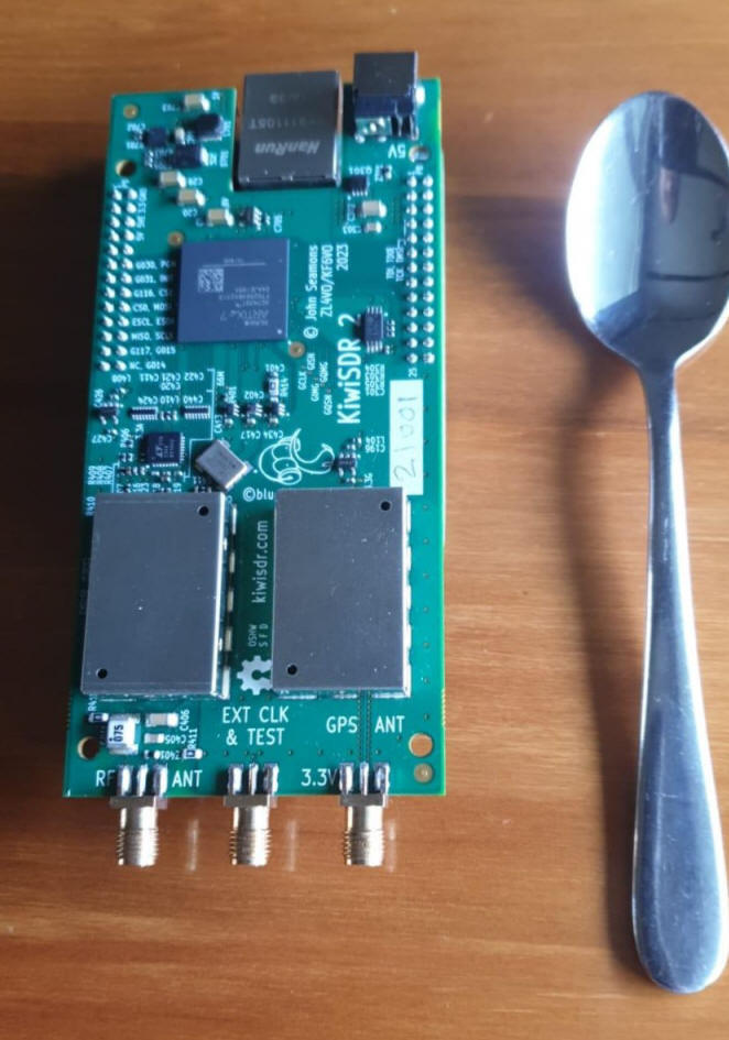
Kiwsdr2 compared with teaspoon
We wish to place the new Kiwisdr in a very quiet location far from civilisation ( way out the back of a farm ). It will use a G5RV, that way we hope it will be semi "automatched" on most of the common ham bands except a few but since its the received Signal to Noise that really matters not so much the "power matching " I dont think optimal matching on receive will mater .
There has been a lot of talk of D.C noise at 5.0v causing performance issues, so as we are going to be a solar powered site, We use 12v with a switched mode power supply to provide 5.0 v , I have placed passive power condition filters on all D.C supply lines . I will have to do the same on the solar regulator but since the potential for noise is bad with solar regulators I may even go linear regulator to eliminate potential RF noise pollution .
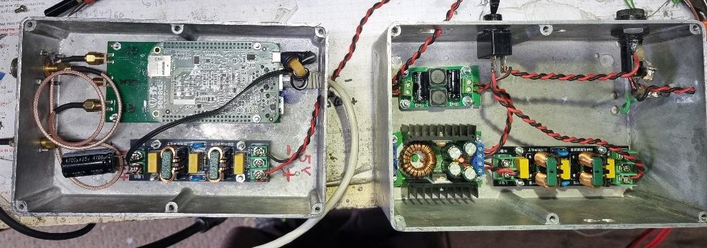
Receiver with outboard SMA for GPS and "N" for G5RV Switched mode power supply and D.C power conditioners
"(I was thinking of going to an all linear power system and run the sdr from a 6 volt battery 6v solar panels, yes you can get them . Low drop out regulator and just make sure any wifi stuff was 5v operation ! )
The new mk2 receiver had been described as having a lower sensitivity than the previous mk 1 design !
so when I had it in my possession, I decided to test its
performance. using my Agilent
N9310A signal generator
"S" Meter reading
No signal Level was S1
S3 WAS -110 dBm
S5 WAS -99 dBm
S7 WAS -86 dBm
S9 WAS -73 dBm
+ 10 WAS -65 dBm
I found with the receiver set to 30 Mhz full "aperture " the minimal detectable
signal at 20 MHz was -114dBm ,at that level the "line signal" just disappeared into the visual background of the
waterfall .
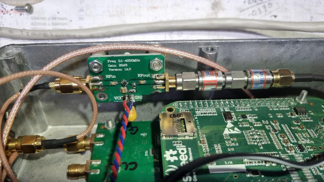
Low noise RF preamp ahead of Kiwisdr, output attenuators to pad the gain down to
12dB but keep low noise figure
The receiver did appear a little deaf for use above 14 Mhz , so I decided
to place a very low noise Rf amp ahead of it . I had some small Chinese rf
preamp boards , of all of them three options were available with
very flat gain curves particularly 0 to 30 MHz.
One a Avantek 1NA 02 ( has 02 as marking ) N.F 2 dB 32 DB gain, 35 mA,
too much , so was deemed unsuitable, and two others ~20 dB,
Phillips BGA2716 (15mA) BGA2709 (23mA) N.F 4 dB 21 dB gain,
RFMD
SBB5089Z N.F 3.9, 19dB ,75mA, All
boards with a flat response and a gain of 20-22 dB,......
manageable..
22 dB is a lot to use on such a wide band reciever , so the gain of the
amp would have to be padded down with fixed attenuation on the OUTPUT SMA ( to maintain the low noise figure
). and try to maintain a good dynamic range in the receiver .
I performed a gain test with the signal generator and the Spectrum Analyser , I
measured the gain at 29.950 MHz with the 12 db pads on the output and it was +12
dB .
I think a good compromise between keeping the receiver N.F low and
not overloading the receiver ! though the Kiwi sdr receiver has a user
selectable switched rf attenuator system . ( if enabled for users to change)
Sometimes the Chinese boards are hard to work out what the active
device is , I went with what I think according to my
performance matching is a Philips BGA2703 ..a 5V , 23mA device, I would love to
try the 1NA02 as it has a low 2.0 db N.F , great at 28 Mhz , but I
dont have enough SMA attenuators to pad the gain down to +10--12 dB !
.
I tried theBGA2709 preamp ahead of the receiver with 6dB attenuation
in the output (~16 dB gain ), now it was no problem to see a signal
of -120 dBm however ! I thought 16 dB gain was still a bit much ,
so I experimented with various degrees of attenuation on the preamp output.
I decided to perform some signal to noise measurements using the Agilent N9310A
signal generator and a commercial S/N meter connected to the audio output
of the SDR receiver ,(from the monitoring computer)
I used a frequency of 20 Mhz and found a pre-amplified
signal of -126dBm disappeared into the SDR waterfall, I could just
make out the FM sidebands at 2.5 Khz deviation with a 1 Khz
modulating tone.
The best s/n on nbfm was at 3.0 KHz .deviation
NO PREAMP 20 Mhz TEST FREQUENCY
dBm input
S/N on Meter
LSB NBFM
-100 20 18
-107 12
_112 12 5
-116 8 2
-119
6
PREAMP WITH 16 dB ATTN ( 6 dB gain ? )
sig in
n A.M A.M
LSB NBFM
-112
12
10.5 19
13
-114
10.5 8.0
18
12
-116
8.0
6.0 17.5
9.5
-118
6.0
4.5 12.5
7.0
-121
4.0
2.0 10
3.0
PREAMP WITH 12 DB ATTN (12 DB GAIN ?)
-112
13 12
20
14
-114
12 10
19
13
-116
10.5 8.5
18.5
12
-118 8.5 7.0
16
10.5
-121
6 4.0
12
6
The "S" meter showed -114 flickering to -115 dBm with and
without a 50 ohm calibration load on the antenna input with the waterfall
displaying 10Khz to 30 Mhz in A.M mode
I then calibrated the "S" meter against the signal generator with no
rf attenuation selected in the SDR. in DBm.
signal strength with RF amp in place.......S3 (-126) S5 (-111) S7 (-99) S9 (-88) S10 (-78) S20 (-68 ) S40 (-48)
The KiwiSDR has quite a flat response RF wise from 1Mhz to 30 Mhz and
its within +/-1 db or so as far as I can test so what you
interpret at 1 Mhz will be within +/- 1db at 28 Mhz, a very
useful remote signal meter !! and the added advantage of visual
representation of the signal strength in form of the waterfall makes it easier
to see weak signals down in the noise .. I suspect that the amount of low noise
pre-amplification is enough to put the receiver "below" ambient noise at 28 Mhz
in a remote rural area and no amount of extra low noise gain is going to improve
the S/N of weak signals but only further reduce the dynamic range of the
receiver .
You can of course switch in more rf attenuation after the RF Preamp if this
feature is enabled on the control screen ..
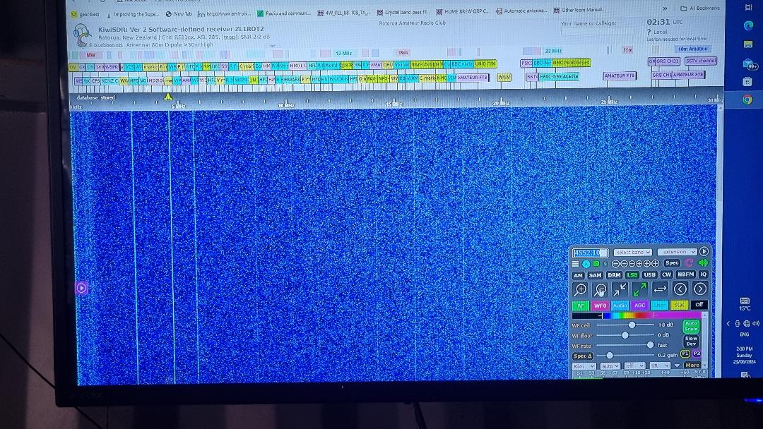
What I discovered was that you must be careful with the placement of the Kiwi module in the diecast box , I mounted the rf unit to the floor with 4 bolts on 6 mm plastic standoffs , . I mounted the rf preamp up on the side of the box above the receiver unit .. If you have any rf leakage you will see vertical lines in the waterfall , I moved the SMA coaxes around and things changed slightly in the waterfall display ..The receiver preamp was terminated with a quality 50 ohm "N" dummy load in both screen shots.
Local internal noise of the micro picked up by Amplified SDR
I found that most of the weak signals picked up from the beagle
micro board were eliminated when I earthed the receiver SMA RF input to
the diecast box below it , leaving a clean waterfall from 0 to 30 MHz .
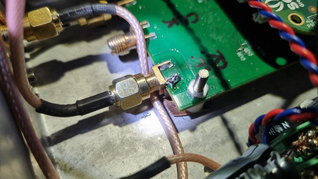
RF ground copper shim soldered to
underneath sma and grounded to diecast box
The power source 5.0 v must be absolutely clean with no noise and I
used brute force filtering after a switch mode voltage
regulator , taking the 12.6 v down to 5.1 volts ,
My Receive setup at
input 12.6V draws 326 mA when running !! that does not
now include the wireless lan so I will have to measure again..
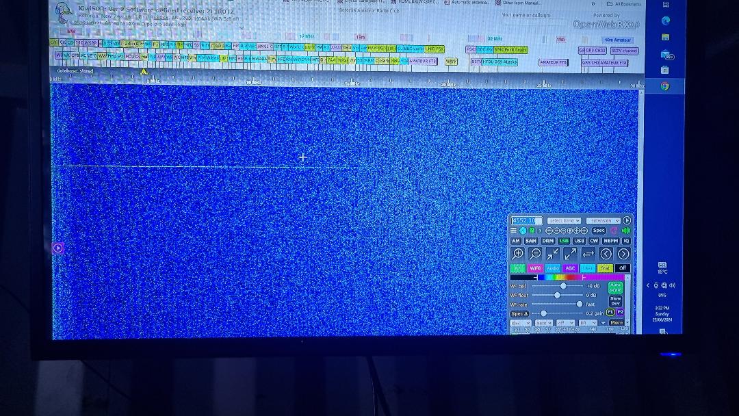
spectrum after grounding RF SMA
socket !! horizontal line is caused by noise spike
connecting N connector to sig generator
I am keen to try the SDR with a 12dB gain low noise preamp in our
wilderness site , connected to a G5RV "multi frequency"
receive antenna hopefully it will not suffer from overload as it is so far
from commercial transmitters , time will tell! Since the RF preamp
output padding attenuators are SMA type we can easily change them to higher
values if overload is a problem .Kiwisdrs seem to get knocked around by
lightening nearby it took out the front end RF and on our Mk1 KIWISDR
but we managed to get the ball grid array rf amp chnged by experts in the field
,with
help from some kind Amateur Radio Tech Chaps at Loop technologies, we got the RF
amp chip replaced and our Club Kiwi SDR is back up working.( Tom
Bevan ZL1THG and Kevin MurphyZL1UJG0 at Loop Technologies in Hamilton.
.By using an RF preamp followed by fixed attenuation of 16 db, this will
be the sacrificial lamb and hopefully protect the receiver from
damage ( piece of cake to change the preamp in the field )
TESTING THE SETUP
Our first test was a bit of a failure ! We used the full sized
G5RV with a balun at the end of the 300 ohm open wire feeder , then
45 m of RG59 coax to the SDR receiver, a short length (1m )of cat 5
cable connected the laptop ( win 10) to the Kiwi SDR., Despite being miles
away from anywhere on the farm., we still got some interference lines on the
waterfall !!??..unacceptable in my books! we did however find the simple
"pinch off" balun
(Joe
Reisert, W1JR designed a method to cross-wind the turns of wire or coax onto a
toroid core)
wound with rg316 on a 30mm ferrite core, had suffered damage
in transit and has broken a wire, Bummer ! the interference
was I suspect ( I hope) ,coming from the laptop as I noticed "signals" appearing
when I used my finger on the mouse pad .
Ok we are going to have to isolate the laptop from the receive area, the only
way to do this is a wireless lan connection from the KIWISDR to the
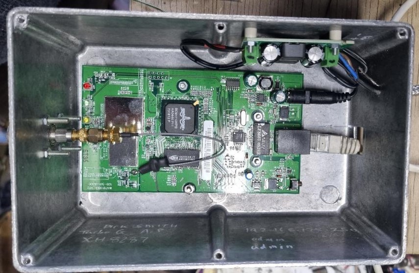
laptop. I have built a wireless lan card A.P, and brute force D.C filtering
into a diecast box with an external "N" connector so we can connect to a
wire parabolic dish 27 db Gain ( only cos I have plenty )
The actual wireless lan was an old 30mW single sma antenna " D.S.E wireless Turbo G Access point" dse code xh8287 12v input 0.5 A . a 10 second hold on the reset button sets it to default 192.168.1.250 ,, username, admin password, admin ..a pair of these will also act as a bridge !! I give you this info if you come across one to use and need to get into it to set it up..
This should enable us to move the laptop right away from the receive
antenna by 100's of meters to eliminate the laptop/ethernet causing
its share of waterfall interference. any left over rf noise will
indicate inadequate sheilding of the diecast box units
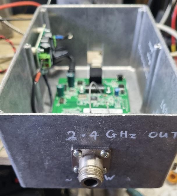
2.4 GHz
Wireless A.P 30mW out
"N" connectors so can use decent coax
2nd Testing Phase
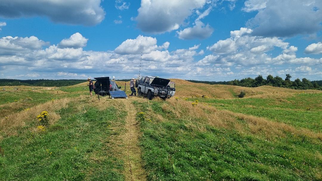
Roger Hill ZL1VCC and Myself went up to our remote site
on the farm out the Back of Mamaku just northwest of Rotorua
where the nearest residence is at least a Km away and the next
closest is about 2 Km away . A truly rural location .. found a high spot
in a reasonably flat site in an unoccupied field and where there was
no cow shit .
we set up the Full size G5RV multiband receive antenna then ran out the
45m of RG59 coax (with a measured loss of 4 db at 30MHz ) and plugged it
into the KiwiSDR receiver .
In order to be able to move the laptop and its potential interference
right out of the field of the H.F. antenna , I opted not to use ethernet
cable connection as it radiates a lot of digital noise despite being a balanced
system, to get around this potential problem , a 27 db grid pack
parabolic antenna was placed on a metal pole next to the receiver assembly
and connected up by a 2m length of RG6 coax to the wireless lan unit
plugged into the KIWISDR Receiver . . The assembly was
turned on and also the little windows 7 Laptop ( 2028 , Acer one ,
Atom processor) and we waited for a wireless connection to the KWISDR log
on screen.
The screen eventuated and we looked at the screen for signs of digitally
generated interference , There were a large number of signals
present, so to remove the laptop from the interference equation we walked
about 100 m down the beam of the parabolic dish , far from the H.F.Antenna and
looked at the screen. Still heaps of signals everywhere and none that has
disappeared ! So next came the boring task of looking at most them to make
sure each was Kosher. The signals that stopped and started and
underwent fading and phasing , we considered ligit !
I was very surprised to see that I couldnt find any obvious interfering
signals , the shielding of the KIWISDR set up was functioning very well
.There was lots of clear blue screen between the signals too , though we
thought we did notice some very very faint bands of colouration
between some of the M.W. broadcast stations and you had to look hard
to see them , not worth even worrying about. We scanned around the bands
listening to H.F Aircraft calling in from over the pacific loud and clear
, I also noticed the random background noise level between
overs was -118dBm ( under a microvolt ! ) according to the "S: meter !! 40m signals were abundant in the afternoon and there were a few weak DX
ones to concentrate on as well .
there were the odd cb signals appearing on 27 Mhz ,these stood out like
the proverbial dogs....bs and there was acres of clean blue screen between
them ..no sign of noise . I suspect the Rf preamp was doing a good job
The Mamaku plateau in July is nowhere to be for any length of time
in winter, we were thankful for a sunny day but the wind bit like a
shark ,so we squeezed into my vehicle . had a coffee from the
thermos and warmed up, then packed everything away and headed
home...... in out enthusiasm we forgot to take pictures of the setup !!
Im Keen as ever to use this site for a remote H.F receive station , there is
no man made noise anywhere to mask signals . All you hear in the " Blue"
screen space between signals is, the random noise of atmospherics
and the odd static crash a radio hams dream !
The biggest obstacle will be, is getting internet to this site .. that may
prevent us setting up the KiwiSDR here however we do
have some other optional sites to try .
This low noise site has enabled me to make and test the receive set
up to be as "interference free" as possible from its own modules ,
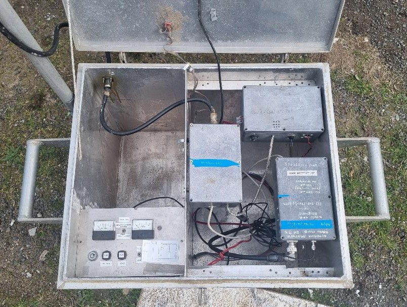
I have now mounterd the sdr components in a portable repeater case I was given many moons ago thanks Bill Goodall . this has plenty of volume and will easily take all the bits we need each module is isolated in its own diecast box with D.C filtering to minimize as much local noise as possible
I have now placed an inexpensive pcm solar panel regulator complete with D,C
input and output filters , to look after the 100Ah deep cycle 12v
battery,
I went for simple pcm charge controller as the solar panels ( two in parallel)
produce 19v at a couple of amps, so the actual loss in the charge system
is not too great , better to have 4-5 amp at 19v than series
connection gaining 38 v at 2.5 A and warming up the solar regulator
.If i had a mppt I could have used series connection but I didnt
have one ... and we can always change over at a later date if the need
arises .
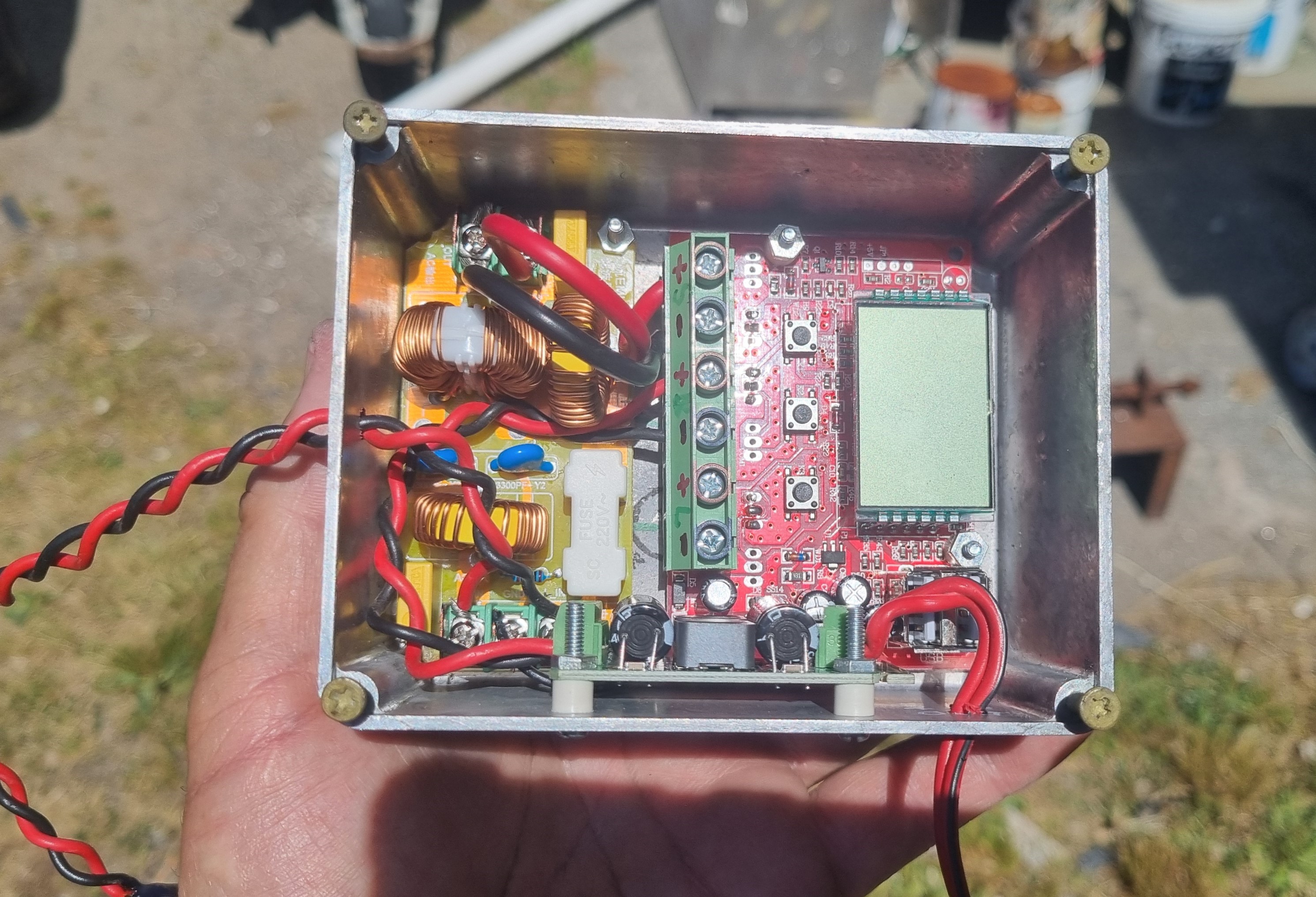
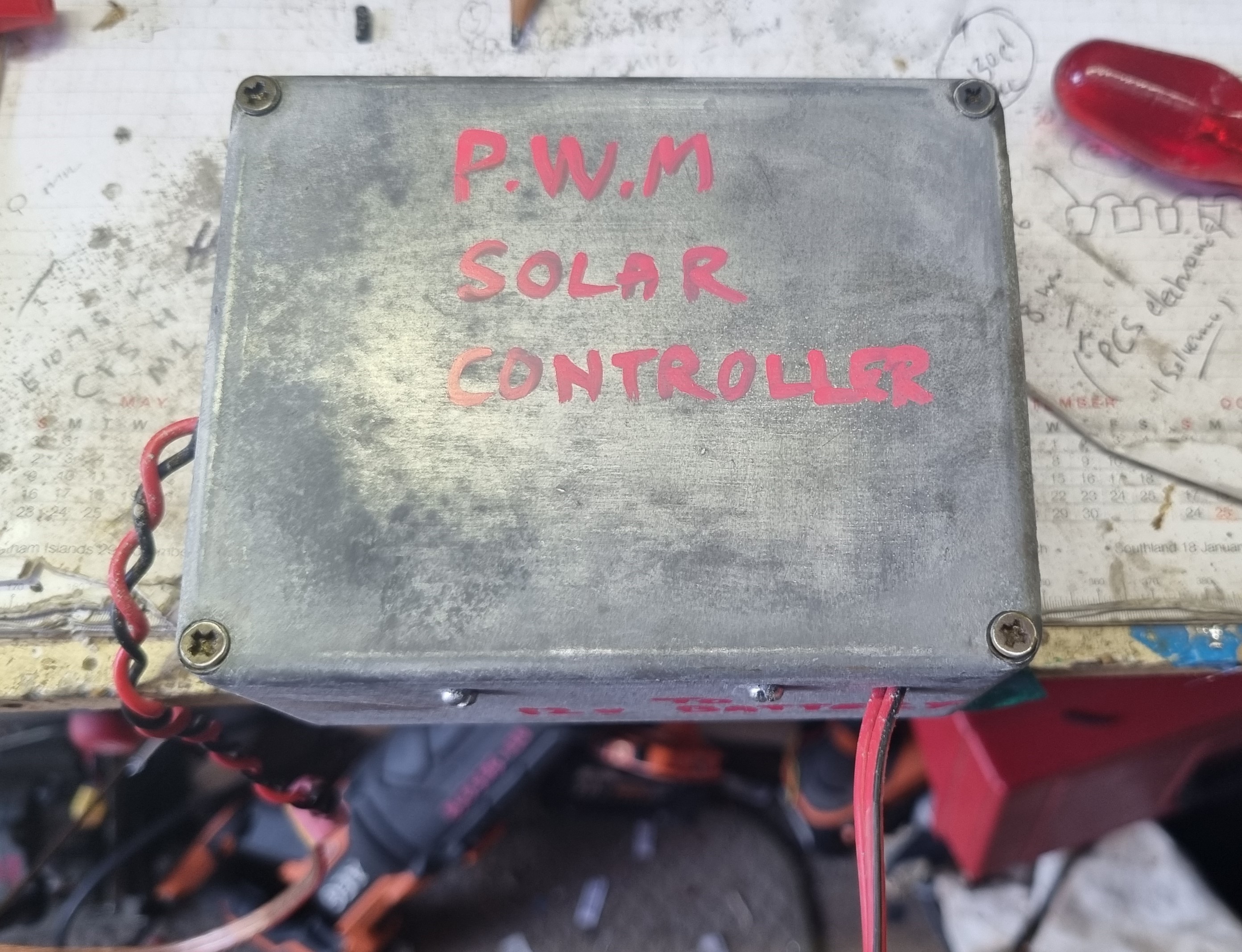
Simple pcm solar regulator with addition D.C filtering on input and output
unit with 2.4 GHZ Lan to minimise ethernet radio interference
.jpg)
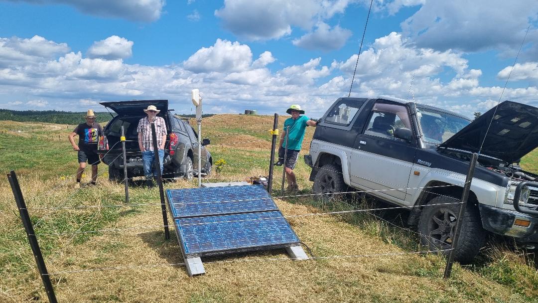
Out in the Boondocks , kms from anybody !
Installation and operation
The SDR was installed at the end of
December 2024 up on a suitable high point where there was some cellphone
reception for the rurual modem .I used the 4g modem stolen out of my bus
and is connected to "Wireless Nation" who will also do the required fixed
I.P address as required for operation. the Modem is connected to a 4g external
antenna mounted on a 1.5m pole along with the gps antenna
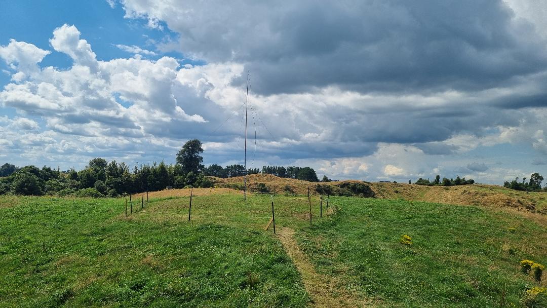
. The G5RV H.F.antenna was erected and that determined the periphery
of the fence (,required to keep the cattle out) if they get in, they
will chew and lick everything, we found out they like the flavour of
300 ohm windowed twin lead !!! so spend extra effort on
a good fence . We have two 30 w 19v solar panels redundant from the 2 meter
linear repeater upgrade so they were paralled up and used . Bright
sun gives us 5A into the battery and 2 A when cloudy . The 4g modem gives
us a couple of megabits connection speed , more than the required 400 Kb
/s required for the set up.
At the moment we have the receiver box on the ground
under the "umbrella " of the H.F antenna ,(it is supposed to be at the end
of the 40m length of RG6 coax away from the antenna to minimise digital
noise pick up ( at a later date) , the 40m length
measure 3dB insertion loss at 50 Mhz on my 50Ohm Agilent VNA .
.jpg)
The captive audience
.jpg)
Branch 33 Rotorua KiwiSDR Mk2 on test
We do have a
"local" interference noise problem ! not a big one but
never the less leakage, despite everything in diecast boxes and in the big
Aluminium portable repeater box , we noticed noise bars and lines on
the remote computer display screen ,they are not so bad as to
degrade the receive performance as we are getting s/n of up to 37/34
at times, but I l would like to eliminate them as a technical challenge.
It was found when the box was opened fully they minimise !!
and when the box lid is down and locked they return ! I suspect there is
capacitive / direct coupling between the lids of the high mounted diecast boxes
and the closed lids, as I can feel the lid deform upward slightly when the box
is fully closed ! So I will remount the diecast boxes
perhaps 100mm lower down into the repeater case and see if that helps stop the
interference being coupled to the lid and being radiated .
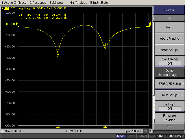
We have, I think an intermod problem ,we have two very strong medium
wave signals one on 819 Khz (-34 dBm) ! and another on 747 Khz
(-37 dBm) both are very strong and may be hammering the rf preamp ,I have notice rf signals
being displayed where there should not be signals, particularly up at 11-10
m region. If you listen to these "signals" in AM mode you will
hear the mixing products of several stations sounding together ...there is no
indication of "Overload" the red O.V display so I attribute it
to the low intercept point of the 10dB low noise broadband rf preamp ,ill
try notching the offending signals with series resonant tuned circuits on
each frequency and see if that fixes the
problem.
the series resonant notch circuit
connects between earth and the centre of the coax .
Will let you know how it performs
'
Make sure you use High "Q" components, air
spaced caps and quality torroids to keep the notches narrow and deep ..
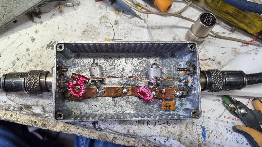
two series resonant circuits
across the antenna coax
philips fuzzy purple torroids with series resonant caps and behive
trimmers
I decided
since I was going to try an Rf preamp with a much higher standing current to try
and cure the perceived intermod problem, I would combine the new RF amp and
notch filters in the same box along with a separate D.C filter board
to keep the rf amp D.C. power " clean" .The only other possible problem is, the amp
has a response to 3 Ghz and I wonder if the cellphone modem polling
signals and WiFi signals are being received on the g5rv and amplified and
pushed into the front end of the Receiver causing a little bit of
interference so I will put a low pass 0-30 Mhz filter on the input
of the notch filter Rf amp and see what effect that has .( used my old Kenwood
0-30 Mhz 100 w unit ).
The pre Amp has a noise figure around 2 db but our feedline from the
antenna through the polyphaser protectors has a loss of 7.0 db at 530 Khz and
0.1 dB at 10 Mhz , Coax feed line was about 2 db at 30Mhz so given
the N.F of the preamp is 2.0 and the other combined losses are just above 2
at 3 0 Mhz , Id say the receiver has just over a 4 dB N.F at 30 Mhz and a N.F
over 7.1 at 530 Khz . No wonder we get such good reception at 10meters .
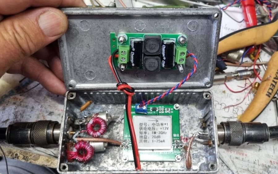
Modified Notch filter with higher intercept low noise RF Amp, 75 mA standing current
Protection against static
The problem of static damage
could be a real issue as we are at a somewhat high altitude 870m
and out in the open. Irrespective of the level of protection,
a lightning strike to the antenna will no doubt blow the lid off the aluminium
box and and destroy everything inside ,so all we can do is try to protect
against induced electric spikes and rain static .The Balun at the end of
the 300 twin lead has a large 470 ohm resistor across it to bleed away any
charge that builds up on the antenna from wind or rain The RG-6 coax
is earthed at the base of the antenna . At the "box" end the coax feeds into 2
modified polyphasers discharge units , in series , connected correctly such that
the induced static charge is forced to discharge to earth via the internal gas
tube , the high voltage 290PF caps ( "D.C" blockers) have been
paralleled with 2.8nf high voltage feedthroughs.
Im hoping that with two polys in series the first one will suffer damage
and the second one may offer more sequential protection . The next
protection "sacrificial lamb" is the RF preamp and finally there is 12 db
of attenuation as well before we get near to the actual Receiver which
also has an increased level of internal protection ....Time will
tell !! ???
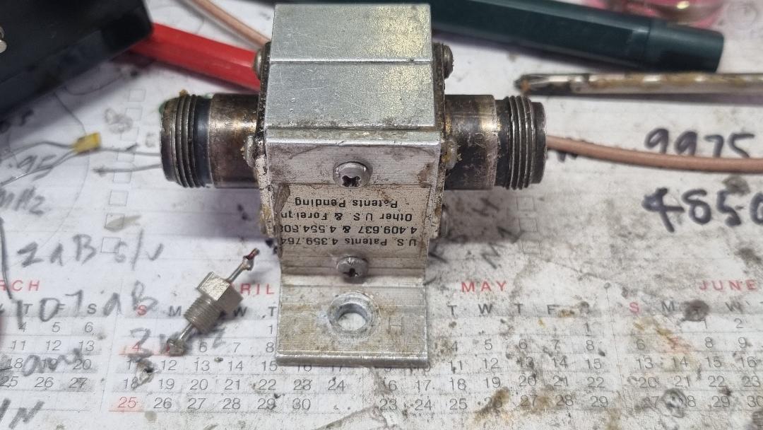
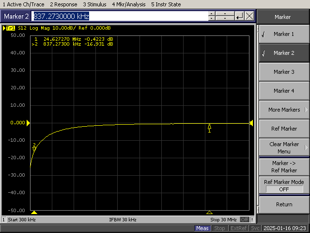
Polyphaser unit Response of original polyphaser ... coupling cap 290 Pf ( VHF ) ??? 16dB loss at 800 KHz
modified unit 2n8 nF feed through cap in
parallel
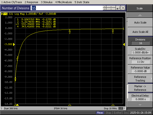
swept response of 2 modified poly phasers in series now
only 6dB at
532 Khz
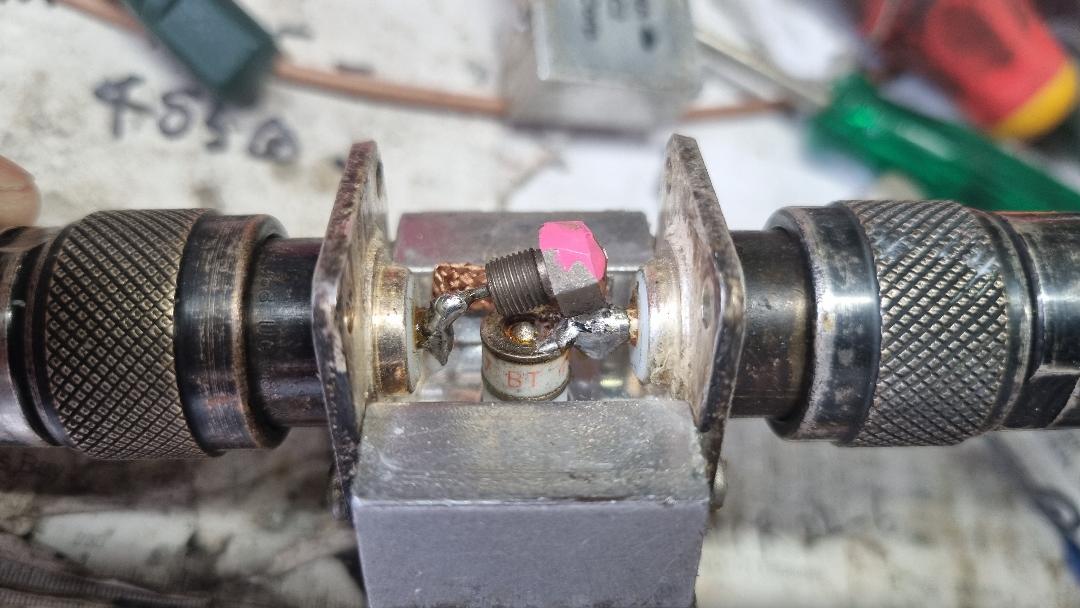
The pink paint was to ascertain the point of contact of the feed
through with the aluminium cover I had to mill some space so there
was no short circuit inside !!
Other
than that we the club are pleased with the result , our original mk
1 kiwisdr has suffered "lightening" damage via the adsl conneced modem so thats
another repair job and get that back on the air for
general use.
Receiver Antenna separation
It was always the idea to get
the receiver as far away from the antenna to minimise the potential
interaction between the two, despite a lot of filtering and
shielding there is still some tiny amount of digital noise eminating from the
receiver box and im still suprised at the performance of the system with the
receiver sitting directly under the H.F antenna .!
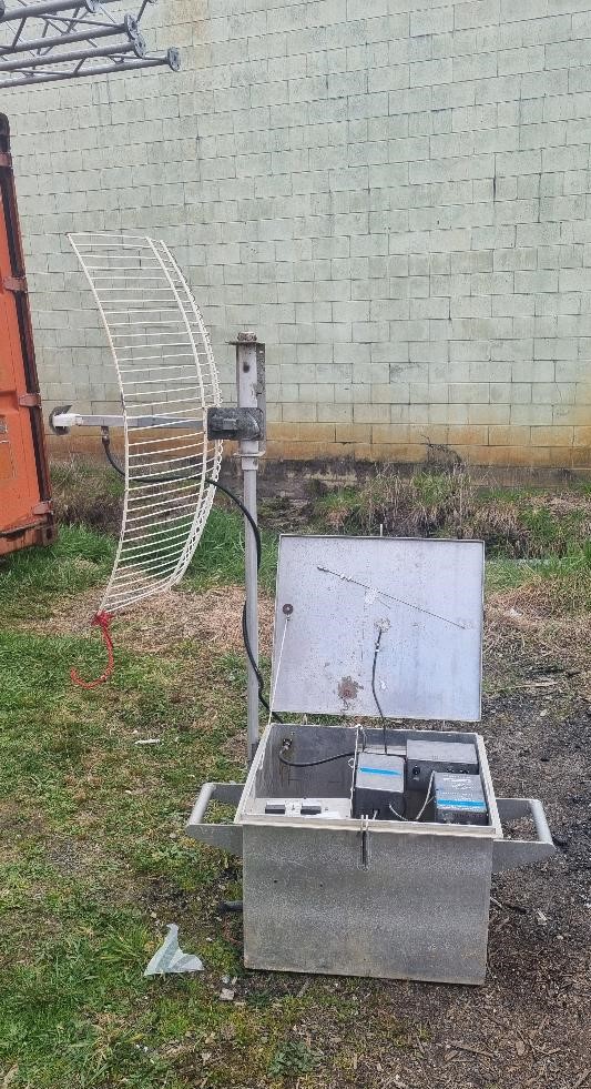
We decided to roll out the receive coax and put the receiver about 40m
away off the end of the dipole on a small "bump" to ensure good 4G reception for
the modem. We constructed a small fenced area and placed the
receiver there along with the solar panels ,the coax was dug into the ground to
minimise interaction with farm stock . Digging that slot by hand was hard
work but I need the exercise . ( we did try it with a 80m coax on another
hillock , good results , there with no "noise" but i
wasnt prepared to dig in that amount of coax into the ground!) so
here it sits for a time .
100A/Hr deep cycle battery and 160 w of solar seems to keep it going ok .( so far)
View from antenna site look off end of the G5RV
The 4g connection is a very expensive way to run the kiwisdr ,we chew
through about 60 Gb a month , but there is no other way to connect and use
a required fixed I.P address , at some stage we will pull it out as
the club cant continue on with this expense $$$ .. Its a shame as it is
without a doubt one of the better low noise Kiwi SDR receivers in New
Zealand . We hear stuff that 90% of other ZL kiwisdrs dont hear
and if you doubt it , pick a weak readable signal on ZL1ROT2 a then go
around the the others ZL Kiwisdr's and only a few if any , will
rival its performance .Make the most of it while you can , we gotta find another
site with an unlimited internet connection.
How much Internet upload bandwidth is used ,short answer from the designer is 320Kb/sec, all channels active and that could theoretically get to 105 GB a month if the 4 channels were used 100% of the time ( highly unlikely ! ) We found later on that we chewed through our 4G modem 60gb plan, in about 3 and a bit weeks which after that dropped to 1.2 Mb but the data speed reduction made no operational difference to the Kiwisdr setup.
Can I suggest that when you first get the receiver installation up and going that you take reading of various signal strengths and note them down with the date the measurement was taken , use stations with consistent signal strengths ...I used local AM radio stations..? 1548 Khz sdr reads -64 dBm , in this way you can see it you have a fault with your receive system at a later date . ( ie cows eating coax and 300 ohm ribbon!